(A) Routine tests of Transformer
(1) Insulation Resistance Test:
Test Purpose:
- Insulation resistance test of transformer is essential to ensure the healthiness of overall insulation of an electrical power transformer.
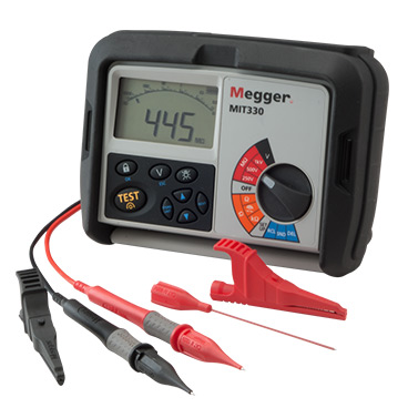
Test Instruments:
- For LT System: Use 500V or 1000V Megger.
- For MV / HV System: Use 2500V or 5000V Megger.
Test Procedure:
- First disconnect all the line and neutral terminals of the transformer.
- Megger leads to be connected to LV and HV bushing studs to measure Insulation Resistance (IR) value in between the LV and HV windings.
- Megger leads to be connected to HV bushing studs and transformer tank earth point to measure Insulation Resistance IR value in between the HV windings and earth.
- Megger leads to be connected to LV bushing studs and transformer tank earth point to measure Insulation Resistance IR value in between the LV windings and earth.
- NB: It is unnecessary to perform insulation resistance test of transformer per phase wise in three phase transformer. IR values are taken between the windings collectively as because all the windings on HV side are internally connected together to form either star or delta and also all the windings on LV side are internally connected together to form either star or delta.
- Measurements are to be taken as follows:
| Type of Transformer | Testing-1 | Testing-2 | Testing-3 |
| Auto Transformer | HV-LV to LV | HV-IV to E | LV to E |
| Two Winding Transformer | HV to LV | HV to E | LV to E |
| Three Winding Transformers | HV to LV | LV to LV | HV to E & LV to E |
- Oil temperature should be noted at the time of insulation resistance test of transformer. Since the IR value of transformer insulating oil may vary with temperature.
- IR values to be recorded at intervals of 15 seconds, 1 minute and 10 minutes.
- With the duration of application of voltage, IR value increases. The increase in IR is an indication of dryness of insulation.
- Absorption Coefficient = 1 minute value/ 15 second value.
- Polarization Index = 10 minutes value / 1 minute value
Tests can detect:
- Weakness of Insulation.
(2) D.C. Resistance or Winding Resistance Test
Test Purpose:
- Transformer winding resistance is measured
- To check any abnormalities like Loose connections, broken strands and High contact resistance in tap changers
- To Calculation of the I2R losses in transformer.
- To Calculation of winding temperature at the end of temperature rise test of transformer.
Test Instrument:
- The Resistance of HV winding LV winding between their terminals are to be measured with
- Precision milliohm meter/ micro ohm meter / Transformer Ohmmeter. OR
- Wheatstone bridge or DC resistance meter.
Method No: 1 (Kelvin Bridge Method for measurement of winding resistance)

Test Procedure:
- The main principle of bridge method is based on comparing an unknown resistance with a known resistance.
- When electric currents flowing through the arms of bridge circuit become balanced, the reading of galvanometer shows zero deflection that means at balanced condition no electric current will flow through the galvanometer.
- Very small value of resistance (in milliohms range) can be accurately measured by Kelvin Bridge method whereas for higher value Wheatstone bridge method of resistance measurement is applied. In bridge method of measurement of winding resistance, the error is minimized.
- All other steps to be taken during transformer winding resistance measurement in these methods are similar to that of current voltage method of measurement of winding resistance of transformer
Method No: 2 (current voltage method of measurement of winding resistance)

Test Procedure:
- The resistance of each transformer winding is measured using DC current and recorded at a ambient temp.
- In this test resistance of winding is measurement by applying a small DC voltage to the winding and measuring the current through the same
- The measured resistance should be corrected to a common temperature such as 75°C or 85°C using the formula: RC=RM x ((CF+CT)/(CF+WT))
- where
- RC is the corrected resistance, RM is the measured resistance
- CF is the correction factor for copper (234.5) or aluminum (225) windings
- CT is the corrected temperature (75°C or 85°C)
- WT is the winding temperature (°C) at time of test
- Before measurement the transformer should be kept in OFF condition at least for 3 to 4 hours so in this time the winding temperature will become equal to its oil temperature.
- To minimize observation errors, polarity of the core magnetization shall be kept constant during all resistance readings.
- Voltmeter leads shall be independent of the current leads to protect it from high voltages which may occur during switching on and off the current circuit.
- The readings shall be taken after the electric current and voltage have reached steady state values. In some cases this may take several minutes depending upon the winding impedance.
- The test current shall not exceed 15% of the rated current of the winding. Large values may cause inaccuracy by heating the winding and thereby changing its resistance.
- For Calculating resistance, the corresponding temperature of the winding at the time of measurement must be taken along with resistance value.
Required Precaution:
- According to IEC 60076-1, in order to reduce measurement errors due to changes in temperature, some precautions should be taken before the measurement is made.
- For Delta connected Winding: for delta-connected transformer, the resistance should be measured for each phase (i.e. R-Y , Y-B & B-R) .Delta is composed of parallel combination of the winding under test and the series combination of the remaining winding .It is therefore recommended to make three measurements for each phase to-phase winding in order obtain the most accurate results.
- For Delta connected windings, such tertiary winding of auto-transformers measurement shall be done between pairs of line terminals and resistance per winding shall be calculated as per the formula: Resistance per Winding = 1.5 X Measured Value
- For Star connected winding: the neutral brought out, the resistance shall be measured between the line and neutral terminal (i.e. R-N , Y-N,B-N) and average of three sets of reading shall be the tested value. For Star connected auto transformers the resistance of the HV side is measured between HV terminal and IV terminal, then between IV terminal and the neutral.
- For Dry type transformers: the transformer shall be at rest in a constant ambient temperature for at least three hours.
- For Oil immersed transformers: the transformers should be under oil and without excitation for at least three hours. In case of tapped windings, above readings are recorded at each tap. In addition, it is important to ensure that the average oil temperature (average of the top and bottom oil temperatures) is approximately the same as the winding temperature. Average oil temperature is to be recorded. Measured values are to be corrected to required temperatures.
- As the measurement current increases, the core will be saturated and inductance will decrease. In this way, the current will reach the saturation value in a shorter time.
- After the current is applied to the circuit, it should be waited until the current becomes stationary (complete saturation) before taking measurements, otherwise, there will be measurement errors.
- The values shall be compared with original test an result which varies with the transformer ratings.
Test Acceptance criteria:
- DC Resistance Should be<=2% Factory Test.
- Test Current <10% Rated Current
Test can detect:
- Short Turns
- Loose Connection of bushing
- Loose Connection or High Contact Resistance on Tap Changer.
- Broken winding stands
Thank you for introducing Omni Controls to me. I visited their site through your blog information. Omni controls offers top quality insulation resistance tester from many leading brands like Megger, Fluke, Sonel Test and Measurement, Extech, AEMC, Reed instruments and more. These all brands offer with the best reliable and accurate test and measurement solutions. You can log on at the website to check the products section to find the best megohmmeter for sale that suits your requirement. I got the equipment on a great deal. I will always recommend them.
ReplyDeleteThank for the amazing blog information about Insulation tester that I recently bought online from Omni Controls Inc. The insulation resistance testers are quite good resistance meters that helped me confirming the condition of the electrical insulation. They are much good insulation testers that are helpful during machinery failure, fire hazard and more. I got insulation tester for sale and megohmmeter for sale to check electrical wiring insulation for the resistance and safety. You can try Megger Insulation Tester, it provides accurate results. Omni Controls Inc. has a vast collection of testers from various brands. Visit the website at https://www.omnicontrols.com.
ReplyDeleteThanks for sharing this detailed insight on insulation resistance testing! I’ve found that using a reliable tool like the fluke 87v max true-rms digital multimeter really helps in getting accurate measurements during transformer diagnostics. It’s crucial to catch insulation issues early to avoid bigger problems down the line.
ReplyDelete