Showing posts with label power transformer. Show all posts

Friday, February 17, 2017

Liquid Resistance stater


Before going in detail about LRS we have to first know what a wound or slip ring induction Motor means and how it operates.


Slip ring Induction motor is similar to that of conventional Induction motor but with high torque capacity.This torque I achieved by making some design changes in rotor. Its rotor has a resistance connected to its winding externally through a slip ring .this resistance can be anything from simple resistance box to liquid resistance box.
Wound Motor

Squirrel cage induction motors draw 500% to over 1000% of full load current (FLC) during starting.While this is not a severe problem for small motors, it is for large (10’s of kW) motors Placing resistance in series with the rotor winding not only decreases start current, locked rotor current (LRC), but also increases the starting torque, locked rotor torque (LRT).

Wound Rotor With Slip Ring
Figure below shows that by increasing the rotor resistance from R0 to R1 to R2, the breakdown torque peak is shifted left to zero speed. Note that this torque peak is much higher than the starting torque available with no rotor resistance (R0) Slip is proportional to rotor resistance, and pullout torque is proportional to slip. Thus, high torque is produced while starting. This high torque is very much beneficial while dealing with heavy loads. The liquid rheostat allows for smooth stepless resistance change.

Torque Vs Slip Characteristics

A liquid rheostat consists of a tank of water mixed with a chemical (Sodium Carbonate) that alters the water’s conductivity in a specific way. It’s important to monitor the water on a regular basis and maintain the desired conductivity by adding water or chemicals as needed. Inserted in the tank are three conductive plates attached to the rotor winding of the induction motor. The motor has these winding brought out to three rings for carbon brush connections.
Liquid Resistance Stater Connection Diagram
The three plates are attached to a mechanism driven by a small reversible motor or manually driven wheel that can lower or raise the plates in the solution. When the plates are most of the way out, the resistance is maximized. When the plates are all they way in, (maximum surface area submerged) the resistance is minimized.

Tuesday, February 7, 2017

Transformer Testinf Part-3 (Ratio Test and vector group test)


(3) Turns Ratio / Voltage Ratio Test:

 Test Purpose:
  • Turns Ratio Test / Voltage Ratio Test are done in Transformer to find out Open Circuited turns, Short Circuited turns in Transformer winding.
  • The voltage ratio is equal to the turn’s ratio in a transformer (V1/V2=N1/N2). Using this principle, the turn’s ratio is measured with the help of a turn’s ratio meter. If it is correct , then the voltage ratio is assumed to be correct
  • This test should be made for any new high-voltage power transformer at the time it is being installed.
  • With use of Turns Ratio meter (TTR), turns Ratio between HV & LV windings at various taps to be measured & recorded.
  • The turn’s ratio is measure of the RMS voltage applied to the primary terminals to the RMS Voltage measured at the secondary terminals.
  • R= Np / Ns
  • Where,
  • R=Voltage ratio
  • Np=Number of turns at primary winding.
  • Ns= Number of turns at secondary Winding.
  • The voltage ratio shall be measured on each tapping in the no-load condition.
 Test Instruments:
  • Turns Ratio meter (TTR) to energies the transformer from a low-voltage supply and measure the HV and LV voltages.
  • Wheatstone Bridge Circuit

 Method No1 Turns Ratio Testing:

 Test Procedure:
  • Transformer Turns Ratio Meter (TTR):
  • Transformer ratio test can be done by Transformer Turns Ratio (TTR) Meter. It has in built power supply, with the voltages commonly used being very low, such as 8, 10 V and 50 Hz.
  • The HV and LV windings of one phase of a transformer (i.e. R-Y & r-n) are connected to the instrument, and the internal bridge elements are varied to produce a null indication on the detector.
  • Values are recorded at each tap in case of tapped windings and then compared to calculated ratio at the same tap.
  • The ratio meter gives accuracy of 0.1 per cent over a ratio range up to 1110:1. The ratio meter is used in a ‘bridge’ circuit where the voltages of the windings of the transformer under test are balanced against the voltages developed across the fixed and variable resistors of the ratio meter.
  • Adjustment of the calibrated variable resistor until zero deflection is obtained on the galvanometer then gives the ratio to unity of the transformer windings from the ratio of the resistors.
  • Bridge Circuit:
Untitled
  • A phase voltage is applied to the one of the windings by means of a bridge circuit and the ratio of induced voltage is measured at the bridge. The accuracy of the measuring instrument is < 0.1 %
  • This theoretical turn ratio is adjusted on the transformer turn ratio tested or TTR by the adjustable
    transformer as shown in the figure above and it should be changed until a balance occurs in the percentage error indicator. The reading on this indicator implies the deviation of measured turn ratio from expected turn ratio in percentage.
  • Theoretical Turns Ratio = HV winding Voltage / LV Winding Voltage
  • % Deviation = (Measured Turn Ratio – Expected Turns Ration) / Expected Turns Ration
  • Out-of-tolerance, ratio test of transformer can be due to shorted turns, especially if there is an associated high excitation current.
  • Open turns in HV winding will indicate very low exciting current and no output voltage since open turns in HV winding causes no excitation current in the winding means no flux hence no induced voltage.
  • But open turn in LV winding causes, low fluctuating LV voltage but normal excitation current in HV winding. Hence open turns in LV winding will be indicated by normal levels of exciting current, but very low levels of unstable output voltage.
  • The turn ratio test of transformer also detects high resistance connections in the lead circuitry or high contact resistance in tap changers by higher excitation current and a difficulty in balancing the bridge.
 Test Caution:
  • Disconnect all transformer terminals from line or load.
  • Neutrals directly grounded to the grid can remain connected

 Method No 2 Voltage Ratio Testing:

  •  This test is done to check both the transformer voltage ratio and tap changer.
  • When “Turns Ratio meter” is not available, Voltage Ratio Test is done at various tap position by applying 3 phases LT (415V) supply on HT side of Power transformer. In order to obtain the required accuracy it is usual to use a ratio meter rather than to energies the transformer from a low-voltage supply and measure the HV and LV voltages.
  • At Various taps applied voltage and Resultant voltages LV side between various Phases and phases& neutral measured with precision voltmeter & noted.
 Test Procedure:
  • With 415 V applied on high voltage side, measure the voltage between all phases on the low voltage side for every tap position.
  • First, the tap changer of transformer is kept in the lowest position and LV terminals are kept open.
  • Then apply 3-phase 415 V supply on HV terminals. Measure the voltages applied on each phase (Phase-Phase) on HV and induced voltages at LV terminals simultaneously.
  • After measuring the voltages at HV and LV terminals, the tap changer of transformer should be raised by one position and repeat test.
  • Repeat the same for each of the tap position separately.
  • At other taps values will be as per the percentage raise or lower at the respective tap positions.
  • In case of Delta/Star transformers the ratio measure between RY-rn, YB-yn and BR-bn.
  • Being Delta/Star transformers the voltage ratio between HV winding and LV winding in each phase limb at normal tap is 33 KV OR 33x√3 = 5.196 ,11 KV / √3 11
  • At higher taps (i-e high voltage steps) less number of turns is in circuit than normal. Hence ratio values increase by a value equal to.5.196 + {5.196 x (no. of steps above normal) x (% rise per each tap)} 100
  • Similarly for lower taps than normal the ratio is equal to 5.196 – {5.196 x (no. of steps above normal) x (% rise per each tap)}100
 Test Acceptance Criteria:
  • Range of measured ratio shall be equal to the calculated ratio ±0.5%.
  • Phase displacement is identical to approved arrangement and transformer’s nameplate.
  • The IEEE standard (IEEE Standard 62) states that when rated voltage is applied to one winding of the transformer, all other rated voltages at no load shall be correct within one half of one percent of the nameplate readings. It also states that all tap voltages shall be correct to the nearest turn if the volts per turn exceed one half of one percent desired voltage .The ratio test verifies that these conditions are met.
  • The IEC60076-1 standard defines the permissible deviation of the actual to declared ratio
  • Principal tapping for a specified first winding pair: the lesser ±0.5% of the declared voltage ratio
  • or 0.1 times the actual short circuit impedance. Other taps on the first winding pair and other winding pair must be agreed upon, and must be lower than the smaller of the two values stated above.
  • Measurements are typically made by applying a known low voltage across the high voltage winding so that the induced voltage on the secondary is lower, thereby reducing hazards while performing the test .For three phase delta/wye or wye/delta transformer, a three phase equivalency test is performed, i.e. the test is performed across corresponding single winding.
 Test can detect:
  • Shorted turns or open circuits in the windings.
  • Incorrect winding connections ,and other internal faults or defects in tap changer

(4) Polarity / Vector group Test

 Purpose of Test:
  • The vector group of transformer is an essential property for successful parallel operation of transformers. Hence every electrical power transformer must undergo through vector group test of transformer at factory site for ensuring the customer specified vector group of transformer.
 Test Instruments:
  • Ratio meter.
  • Volt Meter. A Ratio meter may not always be available and this is usually the case on site so that the polarity may be checked by voltmeter.
 Test Circuit Diagram:
 Untitled
 Test Procedure:
  • The primary and secondary windings are connected together at one point.
  • Connect neutral point of star connected winding with earth.
  • Low-voltage three-phase supply (415 V) is then applied to the HV terminals.
  • Voltage measurements are then taken between various pairs of terminals as indicated in the diagram and the readings obtained should be the phasor sum of the separate voltages of each winding under consideration.
 Condition:(HV side R-Y-B-N and LV Side r-y-b-n)
  • R and r should be shorted.
  • Apply 415 Volt to R-Y-B
  • Measure Voltage between Following Phase and Satisfy Following Condition
Vector GroupSatisfied Following Condition
Dyn1
Rb=Rn+Bn
Bb=By
Yy<Yb
Dyn11
Ry=Rn+Yn
Yb=Yy
Bb<By
Ynd1
RN=Ry+Yn
By=Yy
Yy<Yb
Ynyn0
Bb=Yy
Bn=Yn
RN=Rn+Nn

Transformer Testing part-2 (Insulation resistance )


(A) Routine tests of Transformer

(1) Insulation Resistance Test:

 Test Purpose:
  • Insulation resistance test of transformer is essential to ensure the healthiness of overall insulation of an electrical power transformer.
 Test Instruments:
  • For LT System: Use 500V or 1000V Megger.
  • For MV / HV System: Use 2500V or 5000V Megger.
 Test Procedure:
  • First disconnect all the line and neutral terminals of the transformer.
  • Megger leads to be connected to LV and HV bushing studs to measure Insulation Resistance (IR) value in between the LV and HV windings.
  • Megger leads to be connected to HV bushing studs and transformer tank earth point to measure Insulation Resistance IR value in between the HV windings and earth.
  • Megger leads to be connected to LV bushing studs and transformer tank earth point to measure Insulation Resistance IR value in between the LV windings and earth.
  • NB: It is unnecessary to perform insulation resistance test of transformer per phase wise in three phase transformer. IR values are taken between the windings collectively as because all the windings on HV side are internally connected together to form either star or delta and also all the windings on LV side are internally connected together to form either star or delta.
  • Measurements are to be taken as follows:
Type of TransformerTesting-1Testing-2Testing-3
Auto TransformerHV-LV to LVHV-IV to ELV to E
Two Winding TransformerHV to LVHV to ELV to E
Three Winding TransformersHV to LVLV to LVHV to E & LV to E
  • Oil temperature should be noted at the time of insulation resistance test of transformer. Since the IR value of transformer insulating oil may vary with temperature.
  • IR values to be recorded at intervals of 15 seconds, 1 minute and 10 minutes.
  • With the duration of application of voltage, IR value increases. The increase in IR is an indication of dryness of insulation.
  • Absorption Coefficient = 1 minute value/ 15 second value.
  • Polarization Index = 10 minutes value / 1 minute value
 Tests can detect:
  • Weakness of Insulation.

 (2) D.C. Resistance or Winding Resistance Test

 Test Purpose:
  • Transformer winding resistance is measured
  • To check any abnormalities like Loose connections, broken strands and High contact resistance in tap changers
  • To Calculation of the I2R losses in transformer.
  • To Calculation of winding temperature at the end of temperature rise test of transformer.
 Test Instrument:
  • The Resistance of HV winding LV winding between their terminals are to be measured with
  • Precision milliohm meter/ micro ohm meter / Transformer Ohmmeter. OR
  • Wheatstone bridge or DC resistance meter.
 Method No: 1 (Kelvin Bridge Method for measurement of winding resistance)
 Untitled
Test Procedure:
  • The main principle of bridge method is based on comparing an unknown resistance with a known resistance.
  • When electric currents flowing through the arms of bridge circuit become balanced, the reading of galvanometer shows zero deflection that means at balanced condition no electric current will flow through the galvanometer.
  • Very small value of resistance (in milliohms range) can be accurately measured by Kelvin Bridge method whereas for higher value Wheatstone bridge method of resistance measurement is applied. In bridge method of measurement of winding resistance, the error is minimized.
  • All other steps to be taken during transformer winding resistance measurement in these methods are similar to that of current voltage method of measurement of winding resistance of transformer
 Method No: 2 (current voltage method of measurement of winding resistance)Untitled
Test Procedure:
  • The resistance of each transformer winding is measured using DC current and recorded at a ambient temp.
  • In this test resistance of winding is measurement by applying a small DC voltage to the winding and measuring the current through the same
  • The measured resistance should be corrected to a common temperature such as 75°C or 85°C using the formula: RC=RM x ((CF+CT)/(CF+WT))
  • where
  • RC is the corrected resistance, RM is the measured resistance
  • CF is the correction factor for copper (234.5) or aluminum (225) windings
  • CT is the corrected temperature (75°C or 85°C)
  • WT is the winding temperature (°C) at time of test
  • Before measurement the transformer should be kept in OFF condition at least for 3 to 4 hours so in this time the winding temperature will become equal to its oil temperature.
  • To minimize observation errors, polarity of the core magnetization shall be kept constant during all resistance readings.
  • Voltmeter leads shall be independent of the current leads to protect it from high voltages which may occur during switching on and off the current circuit.
  • The readings shall be taken after the electric current and voltage have reached steady state values. In some cases this may take several minutes depending upon the winding impedance.
  • The test current shall not exceed 15% of the rated current of the winding. Large values may cause inaccuracy by heating the winding and thereby changing its resistance.
  • For Calculating resistance, the corresponding temperature of the winding at the time of measurement must be taken along with resistance value.
 Required Precaution:
  • According to IEC 60076-1, in order to reduce measurement errors due to changes in temperature, some precautions should be taken before the measurement is made.
  • For Delta connected Winding: for delta-connected transformer, the resistance should be measured for each phase (i.e. R-Y , Y-B & B-R) .Delta is composed of parallel combination of the winding under test and the series combination of the remaining winding .It is therefore recommended to make three measurements for each phase to-phase winding in order obtain the most accurate results.
  • For Delta connected windings, such tertiary winding of auto-transformers measurement shall be done between pairs of line terminals and resistance per winding shall be calculated as per the formula: Resistance per Winding = 1.5 X Measured Value
  • For Star connected winding: the neutral brought out, the resistance shall be measured between the line and neutral terminal (i.e. R-N , Y-N,B-N) and average of three sets of reading shall be the tested value. For Star connected auto transformers the resistance of the HV side is measured between HV terminal and IV terminal, then between IV terminal and the neutral.
  • For Dry type transformers: the transformer shall be at rest in a constant ambient temperature for at least three hours.
  • For Oil immersed transformers: the transformers should be under oil and without excitation for at least three hours. In case of tapped windings, above readings are recorded at each tap. In addition, it is important to ensure that the average oil temperature (average of the top and bottom oil temperatures) is approximately the same as the winding temperature. Average oil temperature is to be recorded. Measured values are to be corrected to required temperatures.
  • As the measurement current increases, the core will be saturated and inductance will decrease. In this way, the current will reach the saturation value in a shorter time.
  • After the current is applied to the circuit, it should be waited until the current becomes stationary (complete saturation) before taking measurements, otherwise, there will be measurement errors.
  • The values shall be compared with original test an result which varies with the transformer ratings.
 Test Acceptance criteria:
  • DC Resistance Should be<=2% Factory Test.
  • Test Current <10% Rated Current
 Test can detect:
  • Short Turns
  • Loose Connection of bushing
  • Loose Connection or High Contact Resistance on Tap Changer.
  • Broken winding stands

Types Of Transformer Testing part-1


Introduction:

  • There are various Test required on Transformer to conform performance of Transformer.
  • Mainly two types of transformer are done by manufacturer before dispatching the transformer mainly (1) Type test of transformer and (2) Routine test.
  • In addition some other tests are also carried out by the consumer at site before commissioning and also periodically in regular & emergency basis throughout its life.
  • Transformer Testing mainly classified in
  • Transformer Tests done by Manufacturer
  • (A) Routine Tests
  • (B)Type Tests
  • (C) Special Tests
  • Transformer Tests done at Site
  • (D) Pre Commissioning Tests
  • (E) Periodic/Condition Monitoring Tests
  • (F) Emergency Tests
(A) Routine tests:
  • A Routine test of transformer is mainly for confirming operational performance of individual unit in a production lot. Routine tests are carried out on every unit manufactured.
  • All transformers are subjected to the following Routine tests:
  • Insulation resistance Test.
  • Winding resistance Test.
  • Turns Ration / Voltage ratio Test
  • Polarity / Vector group Test.
  • No-load losses and current Test.
  • Short-circuit impedance and load loss Test.
  • Continuity Test
  • Magnetizing Current Test
  • Magnetic Balance Test
  • High Voltage Test.
  • Dielectric tests
  • Separate source AC voltage.
  • Induced overvoltage.
  • Lightning impulse tests.
  • Test on On-load tap changers, where appropriate.
 (B) Type tests
  • Type tests are tests made on a transformer which is representative of other transformers to demonstrate that they comply with specified requirements not covered by routine tests:
  • Temperature rise test (IEC 60076-2).
  • Dielectric type tests (IEC 60076-3).
 (C) Special tests
  • Special tests are tests, other than routine or type tests, agreed between manufacturer and purchaser.
  • Dielectric special tests.
  • Zero-sequence impedance on three-phase transformers.
  • Short-circuit test.
  • Harmonics on the no-load current.
  • Power taken by fan and oil-pump motors.
  • Determination of sound levels.
  • Determination of capacitances between windings and earth, and between windings.
  • Determination of transient voltage transfer between windings.
  • Tests intended to be repeated in the field to confirm no damage during shipment, for example frequency response analysis (FRA).
(D) Pre commissioning Tests
  • The Test performed before commissioning the transformer at site is called pre commissioning test of transformer. These tests are done to assess the condition of transformer after installation and compare the test results of all the low voltage tests with the factory test reports.
  • All transformers are subjected to the following Pre commissioning tests:
  • IR value of transformer and cables
  • Winding Resistance
  • Transformer Turns Ratio
  • Polarity Test
  • Magnetizing Current
  • Vector Group
  • Magnetic Balance
  • Bushing & Winding Tan Delta (HV )
  • Protective relay testing
  • Transformer oil testing
  • Hipot test

Monday, February 6, 2017

THREE PHASE TRANSFORMER STAR STAR CONNECTION PROS-CONS


The windings of three phase transformers may be connected in by Y or Î” in the same manner as for three single phase transformer.
Since the secondary’s may be connected either in Y or Δ regardless of which connection is used on the primaries, there must be four ways of connecting the windings of a 3-phase transformer for transformation of 3-phase voltages, namely Y-y,Δ -Δ, Y-Δ, and Δ -y.
The inter-connections are made inside of the case so that only the terminal leads need to be brought outside the case:
1.    Star – Star Transformer (Yy0 or Yy6)
2.    Delta – Delta Transformer (Dd0 or Dd6)
3.    Delta – Star Transformer (Dy)
4.    Star – Delta Transformer (Yd) (Grounding Transformer)
5.    Zig-zag Transformer (Yz, Dz) (Grounding Transformer)
6.    Scott (“T” Type) Transformer (Grounding Transformer)

1. Star-Star (Y-y) Connection

Star-Star (Y-y) Transformer Connection

In Primary Winding Each Phase is120°electrical degrees out of phase with the other two phases.
In Secondary Winding Each Phase is120°electrical degrees out of phase with the other two phases.
Each primary winding is magnetically linked to one secondary winding through a common core leg. Sets of windings that are magnetically linked are drawn parallel to each other in the vector diagram. In the Y-Y connection, each primary and secondary winding is connected to a neutral point.
The neutral point may or may not be brought out to an external physical connection and the neutral may or may not be grounded.

Neutral connection
Transformer magnetizing currents are not purely sinusoidal, even if the exciting voltages are sinusoidal. The magnetizing currents have significant quantities of odd-harmonic components. If three identical transformers are connected to each phase and are excited by 60 Hz voltages of equal magnitude, the 60 Hz fundamental components of the exciting currents cancel out each other at the neutral.
This is because the 60 Hz fundamental currents of A, B, and C phase are 120° out of phase with one another and the vector sum of these currents is zero.
The third, ninth, fifteenth and other so-called zero-sequence harmonic currents are in phase with each other; therefore, these components do not cancel out each other at the neutral but add in phase with one another to produce a zero-sequence neutral current, provided there is a path for the neutral current to flow.
Due to the nonlinear shape of the B-H curve, odd-harmonic magnetizing currents are required to support sinusoidal induced voltages. If some of the magnetizing current harmonics are not present, then the induced voltages cannot be sinusoidal.

Y-Y Connection with Grounded Neutral
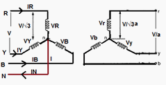
Figure below shows the situation where the primary neutral is returned to the voltage source in a four-wire three-phase circuit. Each of the magnetizing currents labeled IR, IY, and IB contain the 60 Hz fundamental current and all of the odd harmonic currents necessary to support sinusoidal induced voltages.

Transformer Y-Y Connection with Grounded Neutral
The zero-sequence magnetizing currents combine to form the neutral current IN, which returns these odd harmonics to the voltage source. Assuming that the primary voltage is sinusoidal, the induced voltages VR, VY and VB (in both the primary and secondary) are sinusoidal as well.
The connection of primary neutral to the neutral of generator has an add advantage that it eliminates distortion in the secondary phase voltages. If the flux in the core has sinusoidal waveform then it will give sinusoidal waveform for the voltage. But due to characteristic of iron, a sinusoidal waveform of flux requires a third harmonic component in the exciting current. As the frequency of this component is thrice the frequency of circuit at any given constant. It will try to flow either towards or away from the neutral point in the transformer windings.
With isolated neutral, the triple frequency current cannot flow so the flux in the core will not be a sine wave and the voltages are distorted. If primary neutral is connected to generator neutral the triple frequency currents get the path to solve the difficulty. The alternative way of overcoming with this difficulty is the use of tertiary winding of low KVA rating. These windings are connected in delta and provide a circuit in which triple frequency currents can flow. Thus sinusoidal voltage on primary will give sinusoidal voltage on secondary side.
This situation changes if the neutrals of both sets of the primary and secondary windings are not grounded.

Y-Y Connection without Grounded Neutral
If the neutrals of both the primary and the secondary are open-circuited and so there is no path for the zero-sequence harmonic currents to flow and the induced voltages will not be sinusoidal.

Transformer Y-Y Connection without Grounded Neutral
V’R, V’Y, and V’B will not be sinusoidal. This results in distortions of the secondary voltages. The resulting voltage distortion is equivalent to a Y-Y transformer with zero-sequence currents allowed to flow in the primary neutral with an imaginary superimposed primary winding carrying only the zero-sequence currents 180° out of phase with the normal zero-sequence currents.
Analysis of the voltages induced by the ‘‘primary windings’’ is greatly complicated by the fact that the core is highly nonlinear so that each of the individual zero-sequence harmonics currents carried by the phantom primary windings will induce even higher-order harmonic voltages as well.
Fourier analysis can be used to arrive at an approximation of the secondary voltages with an open primary neutral. Taking one phase at a time, the normal magnetizing current for a sinusoidal exciting voltage is plotted from the B-H curve of the transformer. The normal magnetizing current is converted to a Fourier series and then it is reconstructed by removing all of the zero-sequence harmonics.
The resulting exciting current will have a shape different from the normal exciting current, which is then used to construct an induced voltage using the B-H curve in there verse manner that was used to construct the original exciting current.
This process is rather laborious, so suffice it to say that if a Y-Y transformer does not have a neutral path for zero-sequence exciting currents, there will be harmonic voltages induced in the secondary even if the exciting voltage is purely sinusoidal.

Advantages of Y-Y connection
No Phase Displacement
The primary and secondary circuits are in phase; i.e., there are no phase angle displacements introduced by the Y-Y connection. This is an important advantage when transformers are used to interconnect systems of different voltages in a cascading manner. For example, suppose there are four systems operating at 800, 440, 220, and 66 kV that need to be interconnected. Substations can be constructed using Y-Y transformer connections to interconnect any two of these voltages. The 800 kV systems can be tied with the 66 kV systems through a single 800 to 66 kV transformation or through a series of cascading transformations at 440,220 and 66 kV.
Required Few Turns for winding
Due to star connection, phase voltages is (1/√3) times the line voltage. Hence less number of turns is required. Also the stress on insulation is less. This makes the connection economical for small high voltage purposes.
Required Less Insulation Level
If the neutral end of a Y-connected winding is grounded, then there is an opportunity to use reduced levels of insulation at the neutral end of the winding. A winding that is connected across the phases requires full insulation throughout the winding.
Handle Heavy Load
Due to star connection, phase current is same as line current. Hence windings have to carry high currents. This makes cross section of the windings high. Thus the windings are mechanically strong and windings can bear heavy loads and short circuit current.
Use for Three phases Four Wires System
As neutral is available, suitable for three phases four wire system.
Eliminate Distortion in Secondary Phase Voltage
The connection of primary neutral to the neutral of generator eliminates distortion in the secondary phase voltages by giving path to triple frequency currents toward to generator.
Sinusoidal voltage on secondary side
Neutral give path to flow Triple frequency current to flow Generator side thus sinusoidal voltage on primary will give sinusoidal voltage on secondary side.
Used as Auto Transformer
A Y-Y transformer may be constructed as an autotransformer, with the possibility of great cost savings compared to the two-winding transformer construction.
Better Protective Relaying
The protective relay settings will be protecting better on the line to ground faults when the Y-Y transformer connections with solidly grounded neutrals are applied.


Disadvantages of Y-Y connection
The Third harmonic issue
The voltages in any phase of a Y-Y transformer are 1200 apart from the voltages in any other phase. However, the third-harmonic components of each phase will be in phase with each other. Nonlinearities in the transformer core always lead to generation of third harmonic.
These components will add up resulting in large (can be even larger than the fundamental component) third harmonic component.
Overvoltage at Lighting Load
The presence of third (and other zero-sequence) harmonics at an ungrounded neutral can cause overvoltage conditions at light load. When constructing a Y-Y transformer using single-phase transformers connected in a bank, the measured line-to-neutral voltages are not 57.7% of the system phase-to-phase voltage at no load but are about 68% and diminish very rapidly as the bank is loaded.
The effective values of voltages at different frequencies combine by taking the square root of the sum of the voltages squared. With sinusoidal phase-to-phase voltage, the third-harmonic component of the phase-to-neutral voltage is about 60%.
Voltage drop at Unbalance Load
There can be a large voltage drop for unbalanced phase-to-neutral loads. This is caused by the fact that phase-to-phase loads cause a voltage drop through the leakage reactance of the transformer whereas phase-to-neutral loads cause a voltage drop through the magnetizing reactance, which is 100 to 1000 times larger than the leakage reactance.
Overheated Transformer Tank
Under certain circumstances, a Y-Y connected three-phase trans- can produce severe tank overheating that can quickly destroy the transformer. This usually occurs with an open phase on the primary circuit and load on the secondary.
Over Excitation of Core in Fault Condition
If a phase-to-ground fault occurs on the primary circuit with the primary neutral grounded, then the phase-to-neutral voltage on the un faulted phases increases to 173% of the normal voltage. This would almost certainly result in over excitation of the core, with greatly increased magnetizing currents and core losses
If the neutrals of the primary and secondary are both brought out, then a phase-to-ground fault on the secondary circuit causes neutral fault current to flow in the primary circuit. Ground protection re- laying in the neutral of the primary circuit may then operate for faults on the secondary circuit
Neutral Shifting
If the load on the secondary side unbalanced then the performance of this connection is not satisfactory then the shifting of neutral point is possible. To prevent this, star point of the primary is required to be connected to the star point of the generator.
Distortion of Secondary voltage
Even though the star or neutral point of the primary is earthed, the third harmonic present in the alternator voltage may appear on the secondary side. This causes distortion in the secondary phase voltages.
Over Voltage at Light Load
The presence of third (and other zero-sequence) harmonics at an ungrounded neutral can cause overvoltage conditions at light load.
Difficulty in coordination of Ground Protection
In Y-Y Transformer, a low-side ground fault causes primary ground fault current, making coordination more difficult.
Increase Healthy Phase Voltage under Phase to ground Fault
If a phase-to-ground fault occurs on the primary circuit with the primary neutral grounded, then the phase-to-neutral voltage on the UN faulted phase’s increases to 173% of the normal voltage.
If the neutrals of the primary and secondary are both brought out, then a phase-to-ground fault on the secondary circuit causes neutral fault current to flow in the primary circuit.
Trip the T/C in Line-Ground Fault
All harmonics will propagate through the transformer, zero-sequence current path is continuous through the transformer, one line-to-ground fault will trip the transformer.
Suitable for Core Type Transformer
The third harmonic voltage and current is absent in such type of connection with three phase wire system. or shell type of three phase units, the third harmonic phase voltage may be high. This type of connection is more suitable for core type transformers.

Application
This Type of Transformer is rarely used due to problems with unbalanced loads.
It is economical for small high voltage transformers as the number of turns per phase and the amount of insulation required is less.